Today, various industrial robots are developed and used all over the world. However, these industrial robots are specialized in particular operations. In fact, one industrial robot is not able to be designed for operating various tasks. One of the causes is that general-purpose and multifunctional robot hands substituted human manual-handling task are not brought to realization. If these robot hands like human hands are consummated, the applicable field of industrial robots is extended, and the utilization efficiency is improved very much.
A human hand has mechanical handling function such as grab, grip, pinch, push and pull. In addition, it can sense the feeling such as configuration, hard, flexible, smoothness and asperity. In other words, a human hand is a multifunctional and a universal end effector. Many research works on robot hand have been studied all over the world in order to imitate human hand and achieve the similar function to human hand. However, it is not attained that a robot hand system has the coordinative function to human hand’s one yet. For resolving this problem, it is necessity that software system processes various sensors’ information effectively. Additionally, it is also necessity that hardware system has drive mechanism, multi Degrees Of Freedom (DOFs) linkage mechanism and some sensors that allocated in limited spatial restrictions.
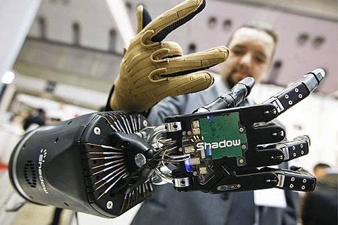
Consequently, we produced the Universal Robot Hand I as shown in Fig.1. The robot hand system has tactile sensors, joint torque sensors, joint angle sensors and the similar structure to human hand’s one. We have studied on the robot hand’s mechanism, the sensory information processing and the kinematic control.
Fig. 1. Universal robot hand I
In this paper, a new robot hand is developed on resulting knowledge for advancing our study. Universal Robot Hand II has actuators, transmission gears, reduction gears, and Torque Limiter Mechanisms in the fingers. Using the Torque Limiter Mechanisms, the fingers can sustain overload not by the gears but by the structure. This is the imitative behavior of a human finger. This paper describes that new small robot hand mechanism has five fingers at the first. At the second, this Torque Limiter Mechanism is introduced. At the third, the effects of Torque Limiter Mechanism are verified in experiments. At the last, results of these experiments are summarized and concluded.
Specifications of developed robot hand
Basic design
This section describes the basic design of developed robot hand. Fig. 2 (left) shows “Universal Robot Hand II”. The height between the lower limit of the palm and the upper limit of the middle finger is 290mm. The width of the robot hand opened up between the thumb and the little finger is 416mm. The size of this robot hand is a little larger than human hand. Thus, this size is enough to imitate human hand workings. The weight of the robot thumb is 0.262kg, the weight of the every other finger is 0.250kg, and the total weight of the robot hand without the pedestal is 1.323kg.
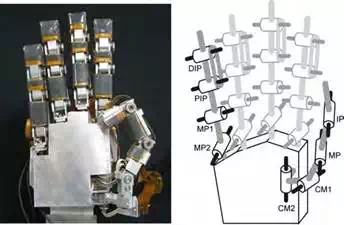
Fig. 2. Universal robot hand II and configuration of DOFs
This robot hand has 16 DOFs. Thumb has four DOFs (the IP, the MP, the CM1 and the CM2 joints), and the other fingers have three DOFs (the PIP, the MP1 and the MP2 joint). Every DIP joint is interlocked with the PIP joint. These DOFs and the movable directions of joints are shown in Fig. 2 (right).
This robot hand has the multi-axis force/torque sensors in every fingertip and tactile sensors on every finger pad. The multi-axis force/torque sensor is able to measure the force and torque at fingertip. This sensor in every fingertip is as shown in Fig.3 (upper right). Tactile sensor is able to measure the pressure distribution on the finger pad. This sensor on every finger pad is as shown in Fig. 3 (lower right).
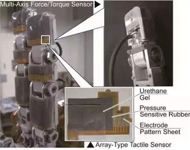
Fig. 3. Multi-axis force/torque sensor (BL AUTOTEC, LTD.) and array-type tactile sensor
The overview of the control system for this robot hand is shown in Fig. 4. This control computer gets the pulse from the encoders in every motor, the value from multi-axis force/torque sensors in every fingertip and the pressure distribution from the array-type tactile sensors on every finger pad. The fingers are controlled through driver circuits according to these data.
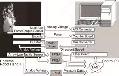
Fig. 4. Control system for universal robot hand
Basic performance
It is shown that the basic performance of the developed robot hand. The movable range of joints is as shown in Table 1. 0 [deg.] is extended position and the flexion direction is the plus direction. This movable range of robot hand is similar or over the human’s one.
| Thumb (deg.) | Others (deg.) | ||
| IP Joint | 0 -110 | DIP Joint | 0 – 95 |
| MP Joint | 0 -110 | PIP Joint | 0 – 95 |
| CM1 Joint | 0 -110 | MP1 Joint | 0 -110 |
| CM2 Joint | 0 -110 | MP2 Joint | 0 -110 |
Table 1. Movable range of each joint
The step responses of every finger are shown in Fig. 5. From this figure, DIP & PIP operates slower than the other joints. As the PIP joint is operated with the DIP joint, the load of DIP & PIP is about twice larger than the other joints’ one. Thus, DIP & PIP operates with about half the angular velocity. Therefore this Universal Robot Hand II has enough response velocity for our future study.
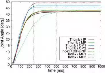
Fig. 5. Result of step response experiments
Superior function
Typically, the robot finger is classified into a hard finger and an elastic finger. In the hard finger, the rotation of the actuator responds plainly to the angle of the joint. In the elastic finger, the fingertip can be moved with elastic members depending on the external force. However, a human finger acts as both a hard finger and an elastic finger depending on a situation. Thus, Torque Limiter Mechanism is fitted into the joint of this Universal Robot Hand II. With this mechanism, driving mechanism in joints is started to skid from setup skidding torque. By implementation with this mechanism, the driving mechanism can be protected against overload, and the robot hand may grasp objects flexibly.
Torque limiter mechanism
Mechanism
Torque Limiter Mechanism is constructed by a fixed plate, a rotating plate and rollers held between these plates as shown in Fig. 6. These rollers are tilted on an angle of degrees. The skidding torque T is expressed in (1).
T rP sin
(1)
where, is the coefficient of the friction between rollers, plates. r is the radius of rollers, and P is the pressure by the adjustment nut. Every 20 joints of this robot hand have this mechanism as shown in Fig. 7.
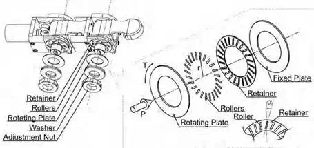
Fig. 6. Inner structure of finger joint with torque limiter mechanism
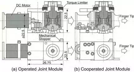
Fig. 7. Cross-section view and side view of torque limiter mechanism
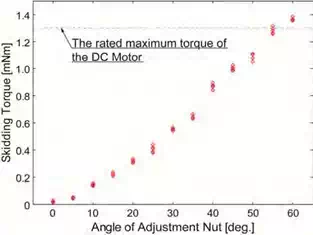
Fig. 8. Angle of adjustment nut vs skidding torque
Fig. 8 shows the relation between the clenched angle of an adjustment nut and the skidding torque. From Fig. 8, the skidding torque is adjustable from maximum to minimum of motor torque. In other word, this finger is able to be adjusted as a hard finger or a passive finger.
Advantages in finger behavior
Torque Limiter Mechanism has some advantages on the operation of the Universal Robot Hand II. The behavior of the finger with the mechanism is shown in Fig. 9 and Fig. 10. The PIP joint and the DIP joint are normally located as shown in Fig. 9 (a). The DIP joint is flexed in conjunction with PIP joint as same degrees. It is thought that excess overload is operated at the distal phalanx. As shown in Fig. 9 (b). If torque by the external force exceeds setup skidding torque, modules of drive gearing are turned over toward the direction of fending off the force to the mechanical stopper as one structure. This mechanism doesn’t only make the actuators to be protected against the overload, but also support the external force mechanistically without output power of actuators by the position of particularity.
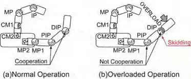
Fig. 9. Overloaded operation with torque limiter mechanism
Flexible grasp with Torque Limiter Mechanism is as shown by Fig. 10. Typically, a robot finger takes the form in Fig. 10 (a) in case of grasping a thin object. This is because that the commonly-used robot hand has engaged DIP and PIP joints in imitation of human joints. On the other hand, in case of grasping a thin object with human fingers, these fingertips are collimated, and increases area of contact between these finger pads. Thus, developed robot hand operates skidding mechanism in the DIP joint. Robot fingertips are collimated, and increases area of contact in Fig. 10 (b). Herewith, developed robot hand doesn’t pinch a thin object with a point contact but with plane contact.
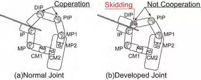
Fig. 10. Clip operation with thin object
Experiments
Alleviation of impact force
Experimental setup
In this experiment, the protection of drive train is verified. The outline of this experiment is shown in Fig. 11. The DIP and the MP2 are fixed with a bump against the mechanical stopper. The PIP is flexed at a tilt, 45 [deg.], and the skidding mechanism is tried and enabled to operate with tuning the adjustment nut. The adjustment nut of MP1 is clenched up to the disabled angle. Drive the MP1 and contact hardly the fingertip to a rigid object. Keep sliding the PIP to a bump against the stopper of the PIP joint and fastening the fingertip on the object for a few seconds. Extend the MP1 to a bump against stopper of the MP1 joint. Values of the fingertip force and the encoder (MP1) are measured during this experiment.
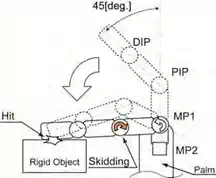
Fig. 11. Impact force experiment
In addition, the adjustment nut of PIP is clenched up and the similar experiment without
Torque Limiter Mechanism is conducted for comparison.
Experimental results
The result of this experiment is shown in Fig. 12. The blue line represents the fingertip force in the case of “Torque Limiter Mechanism is active”, and the black line represents the inactive case. The red line is the value of encoder in the MP1. At 130[step], the fingertip force increases drastically. There is strong evidence that the fingertip touched on a rigid object. At 600[step], the fingertip force decreases precipitously. The fingertip pulled away from the object at this time. As shown by this graph, the case with active skidding mechanism has the lower impact force than the case with inactive one. After that, the fingertip force is kept low during the joint is skidding. The fingertip force in active case converges to the force in inactive case in accordance with the joint is skidded to a bump against the stopper. The fingertip force during this period is lower than converged value. By the result of multiple experiments, the average peak of the force is 0.33 [kgf] in inactive case and 0.20 [kgf] in active case. The peak in active case is drop by about 40% from in inactive case. As identified above, this Torque Limiter Mechanism protects the finger against the accidental overload. Meanwhile, a transition at 700 [step] is impact force by a bump against the stopper at the MP1 joint.
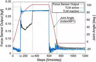
Fig. 12. Transition of encoder contacted against rigid object
Mismatch between joint angle and counted pulse
This skidding mechanism protects the finger against the accidental overload by the experiment in Section 4.1. However, this skidding mechanism has one problem. In the case of the joint is driving and skidding, this problem must be considerable. In this case, the joint angle recognized by the encoder is different from the real joint angle. The encoder is set in every motor, and the joint angle is recognized indirectly by the number of rotations. The motor drives the joint through the skidding mechanism, and the recognized angle has a gap with the real angle in the skidding case. Thus, in this section, compensating method for this gap is validated the evidence.
Experimental setup
In this section, this gap is compensated in the following equation.
where, f is the fingertip force and Fthreshold is the threshold of the fingertip force. t is the motor torque and Tthreshold is the threshold of the torque. is the angle of the joint and i is the control step. The fingertip force f is over the constant value Fthreshold, in other words, the fingertip contacts an object. In addition, the motor torque t is over the constant value Tthreshold, in other words, the torque is able to operate the skidding mechanism. In this instance, as operating the skidding mechanism, the angle is not counted up (down). In other instance, the angle is counted up (down).
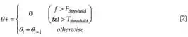
As shown in Fig. 13, the finger hits a rigid object three times from the position of 0 [deg.] using the above method. Meanwhile, the rigid object is set at 91 [deg.], and the finger is extended back to 12.5 [deg.] by measuring the experimental movie. The finger is controlled by the time-control method.
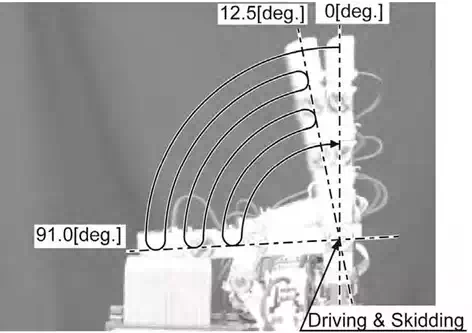
Fig. 13. Outline of experiment about mismatch between joint angle and counted pulse
Experimental results
The result of this experiment is shown by Fig. 14. The red line is the fingertip force. The black line and the blue line is the value of the encoder in MP1. The black line is the compensated data, and the blue line is the raw data. As shown in Fig. 14, the impact force is measured. This has a reason that the DIP and PIP joints of the finger extended to the stopper and the skidding mechanism of the DIP and PIP joints are inactive. Thus, the impact force is not alleviated.
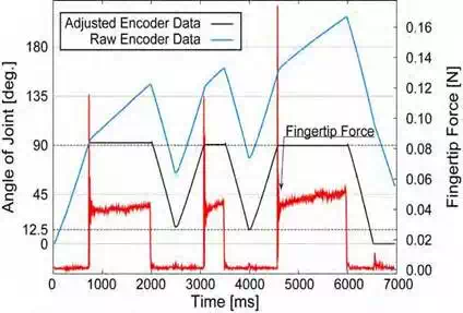
Fig. 14. Transition of fingertip force contacted against rigid object
The angular difference is 1.5 [deg.] between the first tap and the second tap in the compensated data. The angular difference is 0.5[deg.] between the second and the third. After multi-cycle experiments, the angular difference is 2 [deg.] at a maximum by one tap. This compensating method has cumulative difference but is practical. Depending on the desired accuracy of control system, the values of encoders should be reset with a bump against the stopper. The results show that this compensating method is effective.
Conclusions
In this paper, it is declared that the multi-fingered universal robot hand is developed. This robot hand is named “Universal Robot Hand.” This robot hand has 5 fingers, 20 joints and 16 DOFs. This robot hand is a little bigger than a human hand. Every DOF is driven by the
DC motor in the finger. Every joint has Torque Limiter Mechanism. This mechanism is the clutch brake system. The drive mechanism in the joint can be protected against overload by using the skidding mechanism. At the skidding time, the joint angle recognized by the encoder is different from the real joint angle. However the difference can be corrected by the software method.


Comments are closed