It is expected that humanoid robots provide various services to help human daily life such as household works, home security, medical care, welfare and so on(Dominey et al.,2007; Okada et al., 2003; 2005). In order to provide various services, humanoids have multi degree-of-freedom(DOF), sophisticated and complicated structure. These humanoid robots will work under human living environments which are not definable beforehand. So humanoids have to provide their given services under not only the designed environments but also unknown environments. Under unknown environments, robots cannot perform as planned, and they may fall or collide with obstacles. These impacts will wreak several unexpected structure changes such as gear cracks, joint locking, frame distortions and so on. Because of the designed motions are optimized to the robot structure, if the robot structure has changed, the services from robots cannot be provided. Because general users have no expertise knowledge of robots, thus, quick repairs under human living environments cannot be expected. Even in that case, it is expected that the robots should provide services to help human daily life as possible. In the case the humanoid robots cannot get rapid repair service, they have to provide the desired services with their broken body. In addition, using tools to provide some services can be considered as one of the structure changes. Therefore, it is necessary for future humanoids to obtain new motions which can provide the required services with changed structure.
We propose an autonomous motion adaptation method which can be applied to sophisticated and complicated robots represented by humanoids. As a first step, we deal with the simple services based on trajectory control; services can be provided by following the correct path designed by experts. When robot structure has changed, achieving the designed trajectories on changed structure is needed. As the conventional methods, there are two typical approaches. One is the method based on model identification (El-Salam et al., 2005; Groom et al., 1999). Robots locate the occurred changes, identify the changed structure, recalculate inverse kinematics, and then obtain the proper motions. If the changed structure
is identified, inverse kinematics leads the proper motions for new properties of changed structure. However, it is so difficult to identify the complicated structure changes in sophisticated robots. In additions, the available solving methods of inverse kinematics for multi DOF robots is non-existent according to the reference (The Robotics Society of Japan, 2005). So model identification method cannot be applied for humanoids. Another approach is the exploration method (Peters & Schaal, 2007); finding the new motions achieving the desired trajectories after structure has changed. In order to obtain the proper motions achieving the desired trajectories, joint angles are varied by trial and error. Injured robots will obtain the proper motions without complicated model identification, but this approach needs huge exploration costs. New motion adaptation method with low exploration costs and without model identification is needed. In this paper, we show one approach to adapt designed motions to changed structure without model identification.
Proposed methods
We propose a motion adaptation method to generate new proper motions on changed structure without model identification. Even if robot has unobservable changes in mechanical structure, robot generates new motions which achieve the trajectories matching to the desired ones as much as possible.
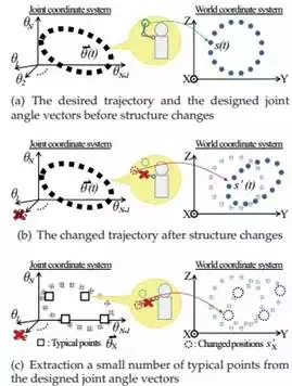
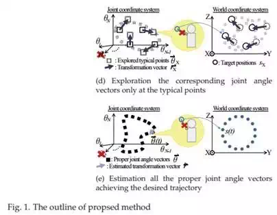
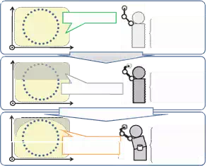
Fig.1 shows the outline of proposed method. Left side shows the robot joint coordinate system and right side shows the world coordinate system. The robot has the designed motions achieving the desired trajectory S. To follow the desired trajectory accuracy, T number of target positions s(t)(1 ≤ t ≤ T) are put on the trajectory. All the designed motions are expressed with time-series joint angle vectors θ(t) which consit of N number of joint angles like this θ (t) = [θ1 (t), θ2 (t), …, θN (t)]. Here, we assume the speed and timing should be controled by other control system, we deal with only the position recovery.
When a joint angle vector θ(t) is given to robot, robot will take a posture, and his end-effector indicates the target position s(t)(Fig.1(a)). The robot can measure the position of the end-effector through the sensors such as cameras or local GPSs. When structure changes have occurred, robot will take another posture even if the same joint angle vector θ (t) is given to the robot(Fig.1(b)). The robot can detect structure changes indirectly through measuring the changed position of end-effector s′ (t). In this case, it is needed to modify all the joint angles to achieve the desired trajectories, but exploration for all the target positions s(t) needs huge exploration costs. So in proposed method, the number of exploration points is reduced using typical points. The robot extracts some combinations of joint angle vectors as typical
| X |
| X |
points θX which representative of all the designed joint angle vectors θ(Fig.1(c)). By applying conventional exploration method only at typical points, the robot obtains the corresponding joint angle vectors θ′′ achieving the target positions sX on changed structure(Fig.1(d)). To generate the other corresponding joint angle vectors, the robot estimates all the proper joint angle vectors θ′′ (t) based on exploration results θ′′ and θX (Fig.1(e)).
The reachable area where the robot can indicate as target positions depends on the robot structure such as frame length, joint range of motion and so on. So structure changes cause the reachable area to be deteriorated. Also it has possibilities that the robot cannot indicate some target positions in designed joint DOF. Generally, humanoids have multi DOF and they have redundant joints which are not used for expressing the designed motions. If structure changes have occured and the target positions cannot be expressed, expansion of joint DOF using redundant joints is needed to extend the robot reachable area for encompassing all the target positions.
Recovery of the desired trajectories with low explration
In order to recover the desired trajectories, proposed adaptation method consists of three phases. Vector Quantization(VQ)(Furui et al., 1998) is applied in order to extract typical
| X |
points θX (Fig.1(c)), Simulated Annearling(SA)(Kirkpatrick, 1984) is applied to explore the corresponding joint angle vectors θ′′ at typical points(Fig.1(d)), and Kriging(Mase & Takeda,
2001) is applied to estimate all the proper joint angle vectors θ′′ (Fig.1(e)).
Extraction of typical points
For cutting costs of exploration, the number of exploration points should be reduced. K(K ≪ T) number of typical points θX (k)(1 ≤ k ≤ K) are extracted from the desgined joint angle vectors θ. In humanoids, because the new motions would be added from users or adjusted for adaptation to environments and so on, typical points cannot be determined beforehand. It is necessary to extract typical points which are represented distribution of all the designed joint angle vectors θ on joint coordinate system.
In this method, several typical points where the target positions are explored are extracted by VQ. VQ is used in many applications such as image compression, voice compression, voice recognition and so on. Some codewords represent a given set of input vectors on coordinate system. K number of typical points θX (k) as codewords resulting from VQ represent all the designed joint angle vectors θ. The number K is determined by quantization distortion which is given based on the number of joints, range of joint motion, accuracy of desired trajectories and so on. Robots can get K number of typical points θX autonomously based on given quantization distortion.
As mentioned, by applying VQ to all the designed joint angle vectors θ distributing on joint coordinate system, some representative joint angle vectors θX are extracted autonomously.
Exploration on typical points
| X |
| X |
By applying conventional exploration method at a typical points θX (k), the corresponding joint angle vectors θ′′ (k) is explored. There is position error between the target position sX (k) and the current indicating position s′ (k). By minimaizing these position errors at all the
| X |
typical points, the proper joint angle vectors θ′′ are aquired. In proposed method, the proper joint angle vectors are explored by SA. SA is one of the famous global optimization method and often used when the search space is discrete. It is considered that the structure changes cause the joint angle coordinate system to go into some discrete changes.
| X |
| X |
By applying SA at a typical point θX (t), a corresponding joint angle vector θ′′ (t) is aquired. From the difference between the original vector θX (k) and the corresponding one θ′′ (k), a
transformation vector rX ( θ(k)) is calculated as (1).
| X |
r(θX (k)) = θ′′ (k) − θX (k).
(1) Each transformation vector is acquired at each typical point. By exploring K target positions
sX , datasets of typical points θX and transformation vectors rX can be aquired.
Estimation of the proper joint angle vectors
All the proper joint angle vectors θ′′ indicating the target positions on changed structure is generated by Kriging; one of the spatial estimation method in geostatistics. Kriging is a technique to predict the value at any point of space from some sample sets of the space points and the values. Mukai(Mukai & Kuriyama, 2005) achieved creating a lot of similar CG motions from limited sample motions by Kriging. By applying interpolation method Kriging, exploration results at typical points can reflect all the designed joint angle vectors.
An estimation transformation vector rˆ(t) which transforms the designed joint angle vector
θ (t) into the proper one θ′′ (t) is estimated by Kriging based on sets of θX and rX .
Based on K sets of typical points θX (k) and transformation vectors rX ( θX (k)), an estimation transformation vector rˆ(θ(t)) at arbitrary joint angle vector θ(t) is calculated as (2).
K
rˆ( θ(t)) = ∑ wk rX ( θX (k)),
k=1
K
∑ wk = 1. (2)
k=1
Here, weight wk is derived from variogram γ which is calculated from K number of sample sets( θX and rX ). A variogram is an indicator of spatial autocorrelation. The variogram for any two samples( θX (i) and θX ( j)(i, j ∈ {1, …, K})) is calculated as (3).
1
γij = 2 Var[ rX (θX (i)) − rX (θX ( j))]. (3)
Here, we define h = θX (i) − θX ( j), the experimental variogram cloud γ∗ is shown as a function of h like (4).
γ∗ ( h) = 1 Var[ r
2 X
( θX
( j) + h) − rX
( θX
( j))], (∀j ∈ {1, …, K}). (4)
The variogram γ is determined by modeling of the experimental variogram cloud γ∗ . We adopt a spherical model which is commonly used in geostatistics. A spherical model is shown as
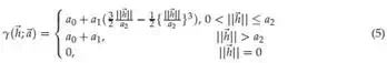
Here, a(a0 , a1 ≥ 0, a2 > 0) shows model parameters and is determined by applying least squares to fit to the experimental variogram cloud. We assume that the joint coordinate system is satisfied locally stationary, an estimation varience of Kriging σ2 is calculated as (6).
σ2 = E ( rˆ(t) − r(t))2
K K K
= − ∑ ∑ wi wj γ( θX (i) − θX ( j)) + 2 ∑ wk γ( θX (k) − θ (t)). (6)
i=1 j=1
k=1
| k=1 |
Hera, E denotes the average. Under the constraints(∑K
wk = 1), weights wk are calculated
by applying Lagrange’s method of undetermined multipliers to minimize the σ2 . The estimation transformation vectors rˆ is calculated from aquired wk and (2).
The proper joint angle vectors θ′′ (t) is calculaed as (7) using the designed joint angle vector
θ (t) and the estimated transformation vector rˆ(θ(t)).
θ′′ (t) = θ(t) + rˆ(θ(t)). (7) By applying (7) to all the designed joint angles θ, the proper joint angle vectors θ′′ achiving
the desired trajectory can be genereted autonomously.
Expansion of joint DOF
For achieving the desired trajectories on changed structure, the joint DOF should be expanded using redundant joints if necessary. When the generated proper joint angle vectors could not achieve the target positions in designed joint DOF, the new joint angle vectors should be explored in expanded joint DOF adding redundant joints.
The concept of deterioration of the reachable area and expansion of joint DOF is shown as
Fig.2. A motion “draw a circle” is designed in 3 DOF consisting of shoulder yaw joint,
Z
Reachable area
X Y
3 DOF Shoulder yaw Shoulder pitch
Elbow yaw
Frame distortion
Z
 Unreachable area
X Y
Expansion of DOF
Z
reachable area
X Y
3 DOF Shoulder yaw Shoulder pitch Elbow yaw
4 DOF Shoulder yaw Shoulder pitch Elbow yaw Waist yaw
Fig. 2. Deterioration of the reachable area and expansion of joint DOF
shoulder pitch joint and elbow yaw joint. The desired trajectory is achieved in designed 3 DOF before structure changes. When the robot structure has changed by frame distortion, the desired trajectory cannot be achieved in designed DOF, because the reachable area has
deteriorated. A redundant waist yaw joint should be added in order to extend the reachable area.
The fewer the joint DOF in which the robot can indicate all the target positions is, the lower exploration costs are. It is difficult for robots to find autonomously the combination of joints in which the robot can indicate all the target positions. In this method, experts of the robots select beforehand the right combination of joints to reach the target positions based on their experimental rule. The prioritization of joints to each end-effector is given in advance. The number of joint DOF is expanded in stages based on the prioritization. An example of
expansion of joint DOF to right hand end-effector on a humanoid is shown as Fig.3. If a trajectory cannot be achived, first, robot generates proper joint angle vectors in the designed DOF using the method as mentioned above. When the robot explores the target positions at
extracted typical points, he can obtain the differences between the target positions and the explored positions. If these differences are not sufficiently-small, then, the robots explore the target positions again in 4 DOF adding waist yaw joint based on given prioritization of joints.
Even if one target position cannot be explored in 4 DOF, the corresponding joint angle vectors are explored in 5 joints adding waist pitch joint. By adding the redundant joints in stages, the corresponding joint angle vectors are acquired with low exploration costs. Proposed method
consisting of VQ and Kriging is independent of joint DOF. Only by exploring in expanded
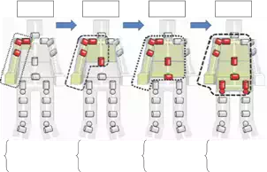
3 DOF 4 DOF 5 DOF 9 DOF
Shoulder pitch Shoulder yaw Elbow yaw
+ Waist yaw + Waist pitch +
Right hip pitch Right hip roll Left hip pitch Left hip roll
Fig. 3. An example of staged expansion of joint DOF on a humanoid
joint DOF at typical points, the proper joint angle vectors are estimated in expanded joint
DOF.
| X |
There is a typical point θX (k) in designed Nd joint DOF. The expanded typical point θ E adding
Nr redundant joints is shown as (8).
| X |
| θ E |
X = (θ1 , θ2 , …, θNd , θNd +1 , …, θNd + Nr ) (8) The transformation vectors rE are acquired in expanded joint DOF by SA. The estimation
transformation vectors rˆE are acquired in expanded joint DOF by Kriging. So the proper joint gle vectors θ′′E are generated in expanded joint DOF.
Experiments
The proposed motion adaptation method is evaluated on simulation. The structure of the target humanoid robot is shown in Fig.4. To exclude the discussion of stability, only the upper
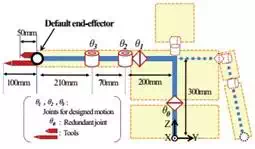

Fig. 4. The structure of the target humanoid
body was modeled. A motion “draw a circle” achieving a desired circular path on Y-Z plane with right hand was designed with 100 time-series joint angle vectors in 3 DOF consisting of shoulder yaw joint θ1 , shoulder pitch joint θ2 and elbow yaw joint θ3 . All the range of joint motion was −130[deg] ≤ θ1 , θ2 , θ3 ≤ +130[deg]. The desired trajectory S was a circular path whose radius was 150mm and center position was (200[mm],-100[mm],300[mm]) on world coorinate system.
So that the quantization distortion on world coordinate system was less than 60mm, 8 typical points were extracted by VQ. If the generated motion in designed 3 DOF cannot achieve the desired trajectory, the new motion is generated according to proposed method in expanded 4
DOF adding waist yaw joint θ0 .
Adaptation to tools
Assuming the users install the tools like a pen, we extended length of the lower arm by 50mm or 100mm as structure changes(Fig.4).
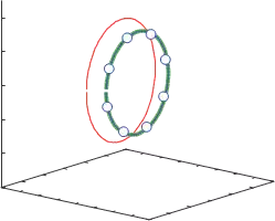
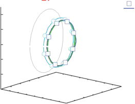
The results of adaptation to using 50mm tool is shown in Fig.5. In Fig.5, green line shows
![]() Desired trajectory
Desired trajectory
![]() Trajectory with 50mm tool [mm]
Trajectory with 50mm tool [mm]
500
![]() Explored typical points
Explored typical points
![]() Generated trajectory
Generated trajectory
400
300
Z
200
100
0
400 350 300
250 200 150
 100
100
-300-400
-200
0 -100
X [mm]
100 50
0 200
Y [mm]
Fig. 5. Observed trajectories with 50mm tool
| X |
the desired trajectory, red dots show the changed trajectory with 50mm tools. Undesired trajectory was expressed with changed structure. 8 blue circles show the explored typical points θ′′ which modified by conventional exploration method SA. 100 proper joint angle vectors θ′′ ware estimated by Kriging based on results of exploration at 8 blue circles. The generated trajectory(blue line) is very consistent with the desired trajectory(green line). The desired trajectory is recovered with about 8% exploration cost on changed structure.
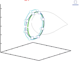
The results of adaptation to using 100mm tool is shown in Fig.6. In Fig.6, red dots show the changed trajectory with 100mm tool. 8 light blue circles show explored typical points in 3 DOF and light blue line shows the generated trajectory in 3 DOF. Attached tool was so long that the robot could not express all the target position in designed 3 DOF. In other words, using the 100mm tool cause deterioration of the reachable area. Even in that case, the generated trajectory(light blue line) represents nearer by the desired one(green line) than the changed one(red dots). The generated trajectory is matched the optimum trajectory acquired from exploration at all the 100 joint angle vectors. It is considered that even if the robot cannot express the desired trajectory on changed structure, by applying porposed method, the robot can generate new motions which achieve the trajectories matching to the desired ones as much as possible.
![]() Desired trajectory
Desired trajectory
Trajectory with 100mm tool [mm]
500
Explored typical points in 3 DOF Generated trajectory in 3 DOF
![]() Explored typical points in 4 DOF Generated trajectory in 4 DOF
Explored typical points in 4 DOF Generated trajectory in 4 DOF
400
300
Z
200
100
0
400 350 300
250 200 150
 100
100
-300-400
-200
0 -100
X [mm]
100 50
0 200
Y [mm]
Fig. 6. Observed trajectories with 100mm tool
Proposed method can apply to correspond not only between the same DOF but also higher DOF, as mention above. So, the robot generates a new motion by exploring in 4 DOF adding redundant waist yaw joint θ0 . In Fig.6, blue squares show the explored typical points and blue line shows the generated trajectory in 4 DOF. The generated trajectory in expanded 4 DOF is nearer by the designed one than that of in 3 DOF, and blue line is very consistent with green line. The desired trajectory is recovered on changed structure by expanding joint DOF.
Adaptation to joint locking
Then, we assumed another change. Another structure change was assumed as elbow yaw joint θ3 locking to 0 degree. Each line shows each trajectory along with Fig.6. Along with
![]() Desired trajectory
Desired trajectory
Trajectory with joint locking [mm]
500
![]() Explored typical points in 3 DOF Generated trajectory in 3 DOF
Explored typical points in 3 DOF Generated trajectory in 3 DOF
Explored typical points in 4 DOF Generated trajectory in 4 DOF
400
300
Z
200
100
0
 400 350 300
250 200 150
100
-300-400
-200
0 -100
X [mm]
100 50
0 200
Y [mm]
Fig. 7. Observed trajectories with joint locking(θ3 = 0[deg])
the adaptation to using 100mm tool, in designed 3 DOF, 8 light blue circles are not on the designed trajectory and the generated trajectory(light blue line) is not matched the desired one(green line). It is to be sure that the generated trajectory represents nearer by the designed one than the changed one, satisfactory trajectory could not be obtained. Joint locking causes degrade of joint DOF, and the reachable area of end-effector has deteriorated. Even in this case, the generated trajectory is matched the optimum one acquired from exploration at all the 100 joint angle vectors, too.
So the robot generates a new motion by exploring in 4 DOF adding redundant waist yaw joint θ0 . The new trajectory(blue line) in expanded 4 DOF is very nearer by the designed one than that of in 3 DOF. Because the generated trajectory is well matched the optimum one which is explored at all the 100 joint angle vectors, it is considered that some of the target positions could not be existed on reachable area even if the joint DOF was expanded to 4 DOF. It is expected that adding the other redundant joints will make the generated trajectory nearer and nearer. Average of position error is about 216mm on failure. The difference between the generated trajectory in 3 DOF and the designed one is about 30mm. The difference 7.4mm is observed by proposed method, which is accomplished about 97% similar trajectory with the desired one.
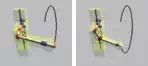
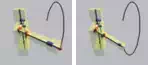
The observed acrual movements of the robot with the designed motion and the generated motions in each joint DOF are shown in Fig.8. The horizontal axis indicates the time of motion t. In 3 DOF, because the robot cannot bend the elbow, the robot cannot express the target


![]() 1 25 50 75 100 t
1 25 50 75 100 t
(a) The desigend motion
![]()


 1 25 50 75 100 t
(b) The generated motion in 3 DOF with joint locking
![]()


 1 25 50 75 100 t
(c) The generated motion in 4 DOF with joint locking
Fig. 8. The obsreved robot motions and trajectories
positions near the body. As the result, the generated trajectory was away from the body. On the other hand, in 4 DOF, in order to express the target positions on near the body, the robot was taking advantage of the redundant waist joint. We looked that robot used redundant waist yaw joint effectively to recover the effect of locked joint.
Conclusion
As a case study of the multi DOF humanoid robots, we introduced the study to execute autonomous motion adaptation against robot mechanical structure changes. To apply for humanoids which have multi DOF and sophisticated complicated structure, we proposed an autonomous motion adaptation method without model identification. We showed that the adaptation method could execute efficiency by exploring the corresponding joint angle vectors at a small number of typical points and estimating all the proper joint angles based on the result in exploration. Using proposed method, the generated trajectories are well matched the desired one on unobservable changed structure. Even if the generated motions wouldn’t have achieved the designed trajectories, it is expected that the new motion achieving the desired trajectories would be generated by exploring in expanded DOF adding redundant joints. Now, we showed experiments only for the trajectory “draw a circle”. In general, humanoid robots should achieve various trajectories to provide various services. Even if the robot has several designed motions to achieve various trajectories, it is expected using VQ that the effective typical points for modifying are extracted and the designed motions can adapt to changed structure efficiently. It is needed to evaluate the effectiveness of proposed method applying for various motions. Now, we deal with only the motions based on trajectory control. This method is not limited control system. The robot chooses the evaluation function based on control system and explores the corresponding joint angle vectors using the evaluation function at typical points, the robot will generate the adapted motions for another control system. It calls for further researches and experiments. We showed the possibility to adapt motions in expanded DOF, but in this paper, adding redundant joints ware determined by experts. It is necessary to consider the joint selection method to expand joint DOF. This method realized to reduce the number of exploration points, but exploration costs increase exponentially with increasing robot joint DOF. There are some humanoid having over 30 DOF, it is difficult to explore in real time. New adaptation method which is not independent on increasing of joint DOF is needed. It calls for further researches and experiments, too.
In our method, stability problems are not resolved. On typical points, by recovering not only position sensor values but also the sensor values observing the stability such as acceleration, gyro, force and so on, the designed trajectories can be recovered in stable condition. In addition, this problems will be resolved in combination with the other methods such as Maufroy(Maufroy et al., 2010), Otoda(Otoda et al., 2009). Further studies are required.


Comments are closed